As a professional China electric high pressure power washer manufacturers and commercial high pressure washers factory, We sincerely invite the global prospective customers to pay a visit and have a good cooperation for a splendid future together.
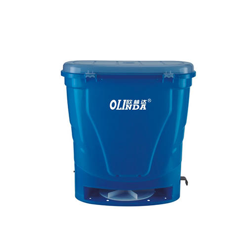
Sale Supply Garden Machinery Fertilizing Machines Factory The initial step in enhancing your garden's productivity is to prepare the soil. Sale Garden...
ALL>>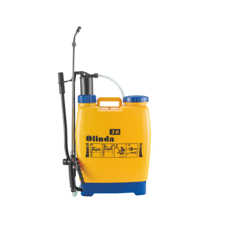
Wholesale High Quality Knapsack Sprayer Exporter Agriculture has come a long way from the traditional methods of farming, with technological advanceme...
ALL>>
No.1008 Qihang Road, Binhai Industry Zone, Jiaojiang, Taizhou, Zhejiang, China.
 0086-576-88133277
 0086-576-88129859
Copyright © Taizhou City Hangyu Plastic Co., Ltd. All Rights Reserved.
Olinda

 英语
英语 中文简体
中文简体


